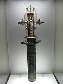
Triode
| This article needs additional citations for verification. Please help improve this article by adding reliable references. Unsourced material may be challenged and removed. (August 2010) |
A triode is an electronic amplification device having three active electrodes. The term most commonly applies to a vacuum tube (or valve in British English) with three elements: the filament or cathode, the grid, and the plate or anode. The triode vacuum tube is the first electronic amplification device. The word is derived from the Greek τρίοδος, tríodos, from tri- (three) and hodós (road, way), originally meaning the place where three roads meet.
Contents[hide] |
[edit] Invention
The original three-element device was patented in 1907[1] by Lee De Forest who developed it from his original two-element 1906 Audion. The Audion did provide amplification. However it was not until around 1912 that other researchers, while attempting to improve the service life of the audion, stumbled on the principle of the true vacuum tube. The name triode appeared later, when it became necessary to distinguish it from other generic kinds of vacuum tubes with more or fewer elements (eg diodes, tetrodes, pentodes etc.). The Audion tubes deliberately contained some gas at low pressure. The name triode is only applied to vacuum tubes which have been evacuated of as much gas as possible.
There was a parallel independent invention of the triode by Austrian Robert von Lieben.[2]
[edit] Operation
The principle of its operation is that, as with a thermionic diode, the heated cathode (either directly or indirectly by means of a filament) causes a space charge of electrons that may be attracted to the positively charged plate (anode in UK parlance) and create a current. Applying a negative voltage (a 'bias') on the control grid will tend to repel some of the (also negatively charged) electrons back towards the cathode: the more negative the voltage on the grid, the smaller the current to the plate. If an AC signal is superimposed on the bias of the grid, an amplified version of the AC signal appears (inverted) across the external impedance in the plate(anode) circuit.
The triode is very similar in operation to the n-channel JFET; it is normally on, and progressively switched off as the grid/gate is pulled increasingly negative of the source/cathode.
[edit] Applications
Although triodes are now largely obsolete in consumer electronics, having been replaced by the transistor, triodes continue to be used in certain high-end and professional audio applications, as well as in microphone preamplifiers and electric guitar amplifiers.
Some guitarists routinely drive their amplifiers to the point of clipping (either grid-current limiting or valve cut-off), in order to produce a desired distortion tone (tube sound). Many people prefer the sound of triodes in such an application, since the distortion of a tube amplifier, which has a "soft" saturation characteristic, can be more pleasing to the ear than that of a typical solid-state amplifier, which through negative feedback is linear up to the limits of its supply voltage and then clips abruptly.
[edit] Characteristics
In triode datasheets, characteristics linking the anode current(Ia) to anode voltage (Va) and grid voltage (Vg) were usually given. From here, designer would choose the operating point of the particular triode.
In the example characteristic shown on the image, if an anode voltage Va of 200 V and a grid voltage bias of -1 volt are selected, a plate (anode) current of 2.25 mA will be present (using the yellow curve on the graph). Changing the grid voltage will change the plate current; by suitable choice of a plate load resistor, amplification is obtained.
In the class A triode amplifier, an anode resistor would be connected between the anode and the positive voltage source. For example, with Ra=10000 Ohms, voltage drop on it will be
VRa=Ia×Ra=22.5 V,
if anode current of Ia=2.25 mA is chosen.
Now, if the input voltage amplitude (at the grid) changes from -1.5 V to -0.5 V (difference of 1 V), anode current will change from 1.2 to 3.3 mA (see image). This will result in anode resistor voltage drop changes from 12 to 33 V (difference of 21 V).
Since grid voltage changes from -1.5 V to -0.5 V, and anode resistor voltage drop from 12 to 33 V, amplification of signal resulted. Amplification factor is 21 - output voltage amplitude divided by input voltage amplitude.
نظرات شما عزیزان:


