


Radar


Radar is an object-detection system which uses electromagnetic waves—specifically radio waves—to determine the range, altitude, direction, or speed of both moving and fixed objects such as aircraft, ships, spacecraft, guided missiles, motor vehicles, weather formations, and terrain. The radar dish, or antenna, transmits pulses of radio waves or microwaves which bounce off any object in their path. The object returns a tiny part of the wave's energy to a dish or antenna which is usually located at the same site as the transmitter.
Practical radar was developed in secrecy during World War II by Britain and other nations. The term RADAR was coined in 1940 by the U.S. Navy as an acronym for radio detection and ranging.[1][2] The term radar has since entered the English and other languages as the common noun radar, losing all capitalization. In the United Kingdom, the technology was initially called RDF (range and direction finding), using the same initials used for radio direction finding to conceal its ranging capability[citation needed].
The modern uses of radar are highly diverse, including air traffic control, radar astronomy, air-defense systems, antimissile systems; nautical radars to locate landmarks and other ships; aircraft anticollision systems; ocean-surveillance systems, outer-space surveillance and rendezvous systems; meteorological precipitation monitoring; altimetry and flight-control systems; guided-missile target-locating systems; and ground-penetrating radar geological observations.
Other systems similar to radar have been used in other parts of the electromagnetic spectrum. One example is "lidar", which uses visible light from lasers rather than radio waves.
Contents[hide] |
[edit] History
Several inventors, scientists, and engineers contributed to the development of radar.
As early as 1886, Heinrich Hertz showed that radio waves could be reflected from solid objects. In 1895 Alexander Popov, a physics instructor at the Imperial Russian Navy school in Kronstadt, developed an apparatus using a coherer tube for detecting distant lightning strikes. The next year, he added a spark-gap transmitter. During 1897, while testing this in communicating between two ships in the Baltic Sea, he took note of an interference beat caused by the passage of a third vessel. In his report, Popov wrote that this phenomenon might be used for detecting objects, but he did nothing more with this observation.[3]
The German Christian Huelsmeyer was the first to use radio waves to detect "the presence of distant metallic objects". In 1904 he demonstrated the feasibility of detecting a ship in dense fog, but not its distance.[4] He received Reichspatent Nr. 165546[5] for his detection device in April 1904, and later patent 169154[6] for a related amendment for also determining the distance to the ship. He also received a British patent on September 23, 1904[7] for the first full Radar application, which he called telemobiloscope.

In August 1917 Nikola Tesla outlined a concept for primitive radar units.[8] He stated, "[...] by their [standing electromagnetic waves] use we may produce at will, from a sending station, an electrical effect in any particular region of the globe; [with which] we may determine the relative position or course of a moving object, such as a vessel at sea, the distance traversed by the same, or its speed."
In 1922 A. Hoyt Taylor and Leo C. Young, researchers working with the U.S. Navy, discovered that when radio waves were broadcast at 60 MHz it was possible to determine the range and bearing of nearby ships in the Potomac River. Despite Taylor's suggestion that this method could be used in darkness and low visibility, the Navy did not immediately continue the work.[9] Serious investigation began eight years later after the discovery that radar could be used to track airplanes.[10]
Before the Second World War, researchers in France, Germany, Italy, Japan, the Netherlands, the Soviet Union, the United Kingdom, and the United States, independently and in great secrecy, developed technologies that led to the modern version of radar. Australia, Canada, New Zealand, and South Africa followed prewar Great Britain, and Hungary had similar developments during the war.[11]
In 1934 the Frenchman Émile Girardeau stated he was building an obstacle-locating radio apparatus "conceived according to the principles stated by Tesla" and obtained a patent (French Patent n° 788795 in 1934) for a working system, a part of which was installed on the Normandie liner in 1935.[12][13][14] During the same year, the Soviet military engineer P.K.Oschepkov, in collaboration with Leningrad Electrophysical Institute, produced an experimental apparatus, RAPID, capable of detecting an aircraft within 3 km of a receiver.[15] The French and Soviet systems, however, had continuous-wave operation and could not give the full performance that was ultimately at the center of modern radar.
Full radar evolved as a pulsed system, and the first such elementary apparatus was demonstrated in December 1934 by the American Robert M. Page, working at the Naval Research Laboratory.[16] The year after the US Army successfully tested a primitive surface to surface radar to aim coastal battery search lights at night. [17] This was followed by a pulsed system demonstrated in May 1935 by Rudolf Kühnhold and the firm GEMA in Germany and then one in June 1935 by an Air Ministry team led by Robert A. Watson Watt in Great Britain. Later, in 1943, Page greatly improved radar with the monopulse technique that was then used for many years in most radar applications.[18]
The British were the first to fully exploit radar as a defence against aircraft attack. This was spurred on by fears that the Germans were developing death rays. The Air Ministry asked British scientists in 1934 to investigate the possibility of propagating electromagnetic energy and the likely effect. Following a study, they concluded that a death ray was impractical but that detection of aircraft appeared feasible.[19] Robert Watson Watt's team demonstrated to his superiors the capabilities of a working prototype and then patented the device (British Patent GB593017).[14][20][21] It served as the basis for the Chain Home network of radars to defend Great Britain. In April 1940, Popular Science showed an example of a radar unit using the Watson-Watt patent in an article on air defence, but not knowing that the U.S. Army and U.S. Navy were working on radars with the same principle, stated under the illustration, "This is not U.S. Army equipment."[22]
The war precipitated research to find better resolution, more portability, and more features for radar, including complementary navigation systems like Oboe used by the RAF's Pathfinder. The postwar years have seen the use of radar in fields as diverse as air traffic control, weather monitoring, astrometry, and road speed control.
[edit] Applications of radar

The information provided by radar includes the bearing and range (and therefore position) of the object from the radar scanner. It is thus used in many different fields where the need for such positioning is crucial. The first use of radar was for military purposes: to locate air, ground and sea targets. This evolved in the civilian field into applications for aircraft, ships, and roads.
In aviation, aircraft are equipped with radar devices that warn of obstacles in or approaching their path and give accurate altitude readings. They can land in fog at airports equipped with radar-assisted ground-controlled approach (GCA) systems, in which the plane's flight is observed on radar screens while operators radio landing directions to the pilot.
Marine radars are used to measure the bearing and distance of ships to prevent collision with other ships, to navigate and to fix their position at sea when within range of shore or other fixed references such as islands, buoys, and lightships. In port or in harbour, vessel traffic service radar systems are used to monitor and regulate ship movements in busy waters. Police forces use radar guns to monitor vehicle speeds on the roads.
Meteorologists use radar to monitor precipitation. It has become the primary tool for short-term weather forecasting and to watch for severe weather such as thunderstorms, tornadoes, winter storms, precipitation types, etc. Geologists use specialised ground-penetrating radars to map the composition of the Earth's crust.
[edit] Principles
A radar system has a transmitter that emits radio waves called radar signals in predetermined directions. When these come into contact with an object they are usually reflected and/or scattered in many directions. Radar signals are reflected especially well by materials of considerable electrical conductivity—especially by most metals, by seawater, by wet land, and by wetlands. Some of these make the use of radar altimeters possible. The radar signals that are reflected back towards the transmitter are the desirable ones that make radar work. If the object is moving either closer or farther away, there is a slight change in the frequency of the radio waves, due to the Doppler effect.
Radar receivers are usually, but not always, in the same location as the transmitter. Although the reflected radar signals captured by the receiving antenna are usually very weak, these signals can be strengthened by the electronic amplifiers that all radar sets contain. More sophisticated methods of signal processing are also nearly always used in order to recover useful radar signals.
The weak absorption of radio waves by the medium through which it passes is what enables radar sets to detect objects at relatively-long ranges—ranges at which other electromagnetic wavelengths, such as visible light, infrared light, and ultraviolet light, are too strongly attenuated. In particular, there are weather conditions under which radar works well regardless of the weather. Such things as fog, clouds, rain, falling snow, and sleet that block visible light are usually transparent to radio waves. Certain, specific radio frequencies that are absorbed or scattered by water vapor, raindrops, or atmospheric gases (especially oxygen) are avoided in designing radars except when detection of these is intended.
Finally, radar relies on its own transmissions, rather than light from the Sun or the Moon, or from electromagnetic waves emitted by the objects themselves, such as infrared wavelengths (heat). This process of directing artificial radio waves towards objects is called illumination, regardless of the fact that radio waves are completely invisible to the human eye or cameras.
[edit] Reflection

Electromagnetic waves reflect (scatter) from any large change in the dielectric constant or diamagnetic constants. This means that a solid object in air or a vacuum, or other significant change in atomic density between the object and what is surrounding it, will usually scatter radar (radio) waves. This is particularly true for electrically conductive materials, such as metal and carbon fiber, making radar particularly well suited to the detection of aircraft and ships. Radar absorbing material, containing resistive and sometimes magnetic substances, is used on military vehicles to reduce radar reflection. This is the radio equivalent of painting something a dark color so that it cannot be seen through normal means (see stealth technology).
Radar waves scatter in a variety of ways depending on the size (wavelength) of the radio wave and the shape of the target. If the wavelength is much shorter than the target's size, the wave will bounce off in a way similar to the way light is reflected by a mirror. If the wavelength is much longer than the size of the target, the target may not be visible due to poor reflection. Low Frequency radar technology is dependent on resonances for detection, but not identification, of targets. This is described by Rayleigh scattering, an effect that creates the Earth's blue sky and red sunsets. When the two length scales are comparable, there may be resonances. Early radars used very long wavelengths that were larger than the targets and received a vague signal, whereas some modern systems use shorter wavelengths (a few centimeters or shorter) that can image objects as small as a loaf of bread.
Short radio waves reflect from curves and corners, in a way similar to glint from a rounded piece of glass. The most reflective targets for short wavelengths have 90° angles between the reflective surfaces. A structure consisting of three flat surfaces meeting at a single corner, like the corner on a box, will always reflect waves entering its opening directly back at the source. These so-called corner reflectors are commonly used as radar reflectors to make otherwise difficult-to-detect objects easier to detect, and are often found on boats in order to improve their detection in a rescue situation and to reduce collisions.
For similar reasons, objects attempting to avoid detection will angle their surfaces in a way to eliminate inside corners and avoid surfaces and edges perpendicular to likely detection directions, which leads to "odd" looking stealth aircraft. These precautions do not completely eliminate reflection because of diffraction, especially at longer wavelengths. Half wavelength long wires or strips of conducting material, such as chaff, are very reflective but do not direct the scattered energy back toward the source. The extent to which an object reflects or scatters radio waves is called its radar cross section.
[edit] Radar equation
The power Pr returning to the receiving antenna is given by the radar equation:
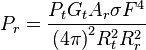
where
- Pt = transmitter power
- Gt = gain of the transmitting antenna
- Ar = effective aperture (area) of the receiving antenna
- σ = radar cross section, or scattering coefficient, of the target
- F = pattern propagation factor
- Rt = distance from the transmitter to the target
- Rr = distance from the target to the receiver.
In the common case where the transmitter and the receiver are at the same location, Rt = Rr and the term Rt² Rr² can be replaced by R4, where R is the range. This yields:
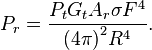
This shows that the received power declines as the fourth power of the range, which means that the reflected power from distant targets is very, very small.
The equation above with F = 1 is a simplification for vacuum without interference. The propagation factor accounts for the effects of multipath and shadowing and depends on the details of the environment. In a real-world situation, pathloss effects should also be considered.
[edit] Doppler effect
Ground-based radar systems used for detecting speeds rely on the Doppler effect. The apparent frequency (f) of the wave changes with the relative position of the target. The doppler equation is stated as follows for vobs (the radial speed of the observer) and vs (the radial speed of the target) and f0 frequency of wave :

However, the change in phase of the return signal is often used instead of the change in frequency. It is to be noted that only the radial component of the speed is available. Hence when a target is moving at right angle to the radar beam, it has no velocity while one parallel to it has maximum recorded speed even if both might have the same real absolute motion.
[edit] Polarization
In the transmitted radar signal, the electric field is perpendicular to the direction of propagation, and this direction of the electric field is the polarization of the wave. Radars use horizontal, vertical, linear and circular polarization to detect different types of reflections. For example, circular polarization is used to minimize the interference caused by rain. Linear polarization returns usually indicate metal surfaces. Random polarization returns usually indicate a fractal surface, such as rocks or soil, and are used by navigation radars.
[edit] Limiting factors
[edit] Beam path and range

The radar beam would follow a linear path in vacuum but it really follows a somewhat curved path in the atmosphere due to the variation of the refractive index of air. Even when the beam is emitted parallel to the ground, it will raise above it as the Earth curvature sink below the horizon. Furthermore, the signal is attenuated by the medium it crosses and the beam disperse as its not a perfect pencil shape.
The maximum range of a conventional radar can either be limited by a number of factors:
- Line of sight, which depends on height above ground.
- The maximum non-ambiguous range (MUR) which is determined by the Pulse repetition frequency (PRF). Simply put, MUR is the distance the pulse could travel and return before the next pulse is emitted.
- Radar sensitivity and power of the return signal as computed in the radar equation. This includes factors such as environmentals and the size (or radar cross section) of the target.
[edit] Noise
Signal noise is an internal source of random variations in the signal, which is generated by all electronic components. Noise typically appears as random variations superimposed on the desired echo signal received in the radar receiver. The lower the power of the desired signal, the more difficult it is to discern it from the noise (similar to trying to hear a whisper while standing near a busy road). Noise figure is a measure of the noise produced by a receiver compared to an ideal receiver, and this needs to be minimized.
Noise is also generated by external sources, most importantly the natural thermal radiation of the background scene surrounding the target of interest. In modern radar systems, due to the high performance of their receivers, the internal noise is typically about equal to or lower than the external scene noise. An exception is if the radar is aimed upwards at clear sky, where the scene is so "cold" that it generates very little thermal noise.
There will be also flicker noise due to electrons transit, but depending on 1/f, will be much lower than thermal noise when the frequency is high. Hence, in pulse radar, the system will be always heterodyne. See intermediate frequency.
[edit] Interference
Radar systems must overcome unwanted signals in order to focus only on the actual targets of interest. These unwanted signals may originate from internal and external sources, both passive and active. The ability of the radar system to overcome these unwanted signals defines its signal-to-noise ratio (SNR). SNR is defined as the ratio of a signal power to the noise power within the desired signal.
In less technical terms, SNR compares the level of a desired signal (such as targets) to the level of background noise. The higher a system's SNR, the better it is in isolating actual targets from the surrounding noise signals.
[edit] Clutter
Clutter refers to radio frequency (RF) echoes returned from targets which are uninteresting to the radar operators. Such targets include natural objects such as ground, sea, precipitation (such as rain, snow or hail), sand storms, animals (especially birds), atmospheric turbulence, and other atmospheric effects, such as ionosphere reflections, meteor trails, and three body scatter spike. Clutter may also be returned from man-made objects such as buildings and, intentionally, by radar countermeasures such as chaff.
Some clutter may also be caused by a long radar waveguide between the radar transceiver and the antenna. In a typical plan position indicator (PPI) radar with a rotating antenna, this will usually be seen as a "sun" or "sunburst" in the centre of the display as the receiver responds to echoes from dust particles and misguided RF in the waveguide. Adjusting the timing between when the transmitter sends a pulse and when the receiver stage is enabled will generally reduce the sunburst without affecting the accuracy of the range, since most sunburst is caused by a diffused transmit pulse reflected before it leaves the antenna.
While some clutter sources may be undesirable for some radar applications (such as storm clouds for air-defence radars), they may be desirable for others (meteorological radars in this example). Clutter is considered a passive interference source, since it only appears in response to radar signals sent by the radar.
There are several methods of detecting and neutralizing clutter. Many of these methods rely on the fact that clutter tends to appear static between radar scans. Therefore, when comparing subsequent scans echoes, desirable targets will appear to move and all stationary echoes can be eliminated. Sea clutter can be reduced by using horizontal polarization, while rain is reduced with circular polarization (note that meteorological radars wish for the opposite effect, therefore using linear polarization the better to detect precipitation). Other methods attempt to increase the signal-to-clutter ratio.
Constant False Alarm Rate (CFAR, a form of Automatic Gain Control, or AGC) is a method relying on the fact that clutter returns far outnumber echoes from targets of interest. The receiver's gain is automatically adjusted to maintain a constant level of overall visible clutter. While this does not help detect targets masked by stronger surrounding clutter, it does help to distinguish strong target sources. In the past, radar AGC was electronically controlled and affected the gain of the entire radar receiver. As radars evolved, AGC became computer-software controlled, and affected the gain with greater granularity, in specific detection cells.

Clutter may also originate from multipath echoes from valid targets due to ground reflection, atmospheric ducting or ionospheric reflection/refraction (e.g. Anomalous propagation). This clutter type is especially bothersome, since it appears to move and behave like other normal (point) targets of interest, thereby creating a ghost. In a typical scenario, an aircraft echo is multipath-reflected from the ground below, appearing to the receiver as an identical target below the correct one. The radar may try to unify the targets, reporting the target at an incorrect height, or—worse—eliminating it on the basis of jitter or a physical impossibility. These problems can be overcome by incorporating a ground map of the radar's surroundings and eliminating all echoes which appear to originate below ground or above a certain height. In newer Air Traffic Control (ATC) radar equipment, algorithms are used to identify the false targets by comparing the current pulse returns, to those adjacent, as well as calculating return improbabilities due to calculated height, distance, and radar timing.
[edit] Jamming
Radar jamming refers to radio frequency signals originating from sources outside the radar, transmitting in the radar's frequency and thereby masking targets of interest. Jamming may be intentional, as with an electronic warfare (EW) tactic, or unintentional, as with friendly forces operating equipment that transmits using the same frequency range. Jamming is considered an active interference source, since it is initiated by elements outside the radar and in general unrelated to the radar signals.
Jamming is problematic to radar since the jamming signal only needs to travel one-way (from the jammer to the radar receiver) whereas the radar echoes travel two-ways (radar-target-radar) and are therefore significantly reduced in power by the time they return to the radar receiver. Jammers therefore can be much less powerful than their jammed radars and still effectively mask targets along the line of sight from the jammer to the radar (Mainlobe Jamming). Jammers have an added effect of affecting radars along other lines of sight, due to the radar receiver's sidelobes (Sidelobe Jamming).
Mainlobe jamming can generally only be reduced by narrowing the mainlobe solid angle, and can never fully be eliminated when directly facing a jammer which uses the same frequency and polarization as the radar. Sidelobe jamming can be overcome by reducing receiving sidelobes in the radar antenna design and by using an omnidirectional antenna to detect and disregard non-mainlobe signals. Other anti-jamming techniques are frequency hopping and polarization. See Electronic counter-counter-measures for details.
Interference has recently become a problem for C-band (5.66 GHz) meteorological radars with the proliferation of 5.4 GHz band WiFi equipment.[citation needed]
[edit] Radar signal processing
[edit] Distance measurement
[edit] Transit time


One way to measure the distance to an object is to transmit a short pulse of radio signal (electromagnetic radiation), and measure the time it takes for the reflection to return. The distance is one-half the product of the round trip time (because the signal has to travel to the target and then back to the receiver) and the speed of the signal. Since radio waves travel at the speed of light (186,000 miles per second or 300,000,000 meters per second), accurate distance measurement requires high-performance electronics.
In most cases, the receiver does not detect the return while the signal is being transmitted. Through the use of a device called a duplexer, the radar switches between transmitting and receiving at a predetermined rate. The minimum range is calculated by measuring the length of the pulse multiplied by the speed of light, divided by two. In order to detect closer targets one must use a shorter pulse length.
A simi
نظرات شما عزیزان:

